Media
- Media
- Analog Devices: Next-Generation Building Controller, Unlocking a New Smart Experience
Analog Devices: Next-Generation Building Controller, Unlocking a New Smart Experience
With the continuous advancement of science and technology and people’s pursuit of higher quality of life, smart buildings have become a critical direction for future architectural development. The emergence of smart buildings is mainly to intelligently control and optimize the building environment. The seamless integration of structure, equipment, and services enhances energy efficiency, safety, comfort, and sustainability, driving the development of smart cities.
Meanwhile, global challenges such as urbanization and climate change are accelerating the demand for smart buildings. By using multiple data sources within secure, scalable, and interconnected systems, effective decisions can be made in real time, creating more energy-efficient and effective environments. High-precision data allows for real-time interactions and responses between buildings and users, creating safe and efficient spaces applicable to commercial, residential, and even industrial sectors.
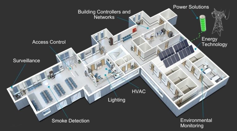
Figure 1. Building Control System
Building automation systems can maximize comfort, safety and energy efficiency while supporting scalability. From HVAC to lighting, maximizing work performance requires a complex and reliable network that provides accurate data and connections. As building control systems become more localized, platform solutions are emerging that can save time and costs. These solutions, with their low power consumption and flexibility, make buildings easier to reconfigure to meet evolving needs.
ADI’s building automation system technology is designed to manage the rapid increase in connected devices, facilitating the development of smart buildings. These smaller, scalable, low-power solutions support the use of building control platform approaches to monitor, control, and reconfigure on a local or higher level. They are not only suitable for existing building network topologies and standards but also to new, more advanced technology.
As shown in Figure 2, the building automation system is divided into four layers. The first layer from top to bottom is the management layer, where the server equipment and upper-layer management technology are implemented. This layer enables the current working status of each subsystem to be accessed through servers on a computer.
The second layer is the Network Distribution/Integration Layer. This layer interfaces with each control device, and the subsystems within the integration layer may each manage a smaller system, such as lighting, temperature, or HVAC systems. This arrangement not only facilitates categorized management but also allows for the expansion into more complex systems.
Next is the Controller layer, which delves into the decentralized control discussed above; this is where the core devices for distributed management are located. It can be understood as an on-site brain through which decisions are made quickly. For example, if high temperature is detected, it can use the built-in PID algorithm to drive the fans to work faster, thus lowering the temperature. Therefore, the building controller has a large number of analog sensor I/Os.
The bottom layer is the Field Sensor layer. This layer connects to a multitude of sensors to detect the condition of the site or the entire building, making it crucial for information gathering. There is also a last equipment layer, which includes devices like compressors. This layer is sometimes also connected to the controller layer, essentially comprising the on-site equipment.
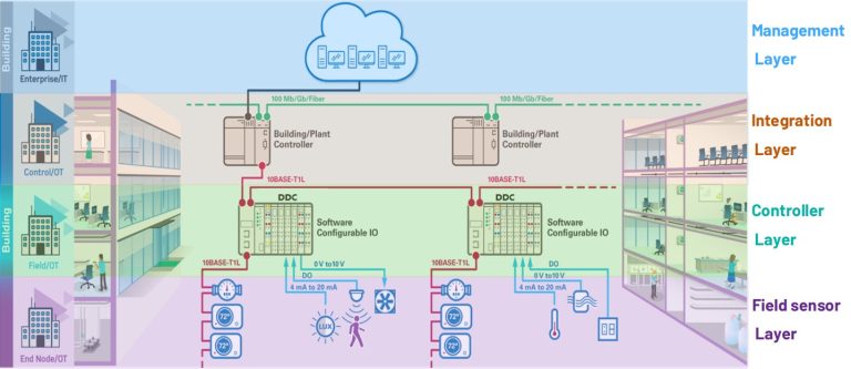
Figure 2: Building automation system
Modern building automation systems connect elevators, water pumps, fans, air conditioning, HVAC, and lighting equipment for online monitoring. By installing appropriate sensors, temperature, humidity, and lighting levels can be automatically controlled via switches. As the core device in building automation, the building controller (Direct Digital Controller) receives settings from the supervisory system, real-time data from onsite sensors, and outputs control actions, thereby implementing a true closed-loop control system.
Building controllers, also known as digital controllers, primarily sense the input/output of external analog and digital signals. They are equipped with numerous PID control units required for building automation, which control the entire system. Analog Devices Inc. (ADI) offers a wide range of products in building control systems, generally categorized into Software IO, 10Base-T1L, RS-485, and SPoE, among others.
ADI Product Introduction
Inputs/outputs and analog input/output are key signal interfaces and action interfaces for building controller devices. Traditional control systems use a complex set of channel modules, analog and digital signal converters. Separate wired inputs/outputs to communicate with sensors require costly and labor-intensive manual configuration.
ADI’s launch of I/O chips for building control and process automation greatly reduces the difficulty of design. It uses common interfaces to respond to different needs, greatly simplifying the complexity of hardware design. Additionally, they enable manufacturers and industrial operators to flexibly configure channel functions on-site.
Having partnered with ADI for over thirty years, Excelpoint has developed multiple solutions tailored to meet customer application needs. Focusing on two types of transmission links, Excelpoint currently highlights the AD74412R/AD74413R as key recommendations in the market.
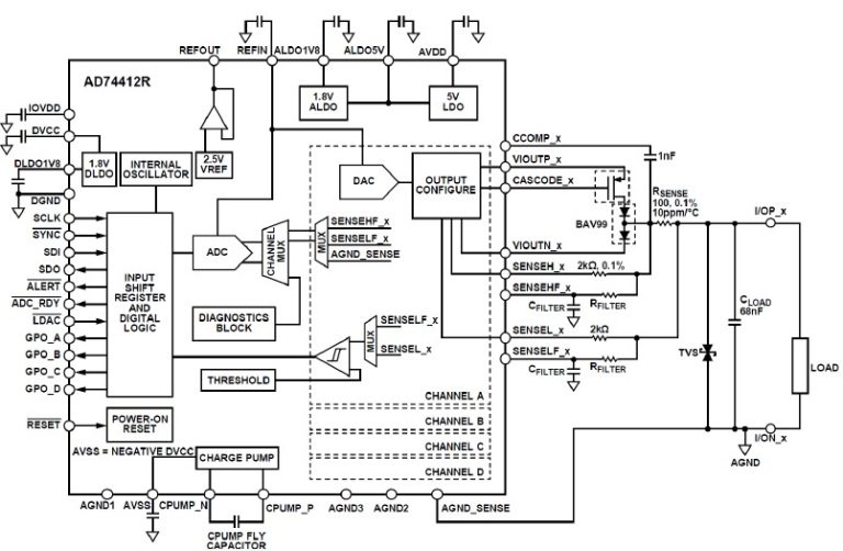
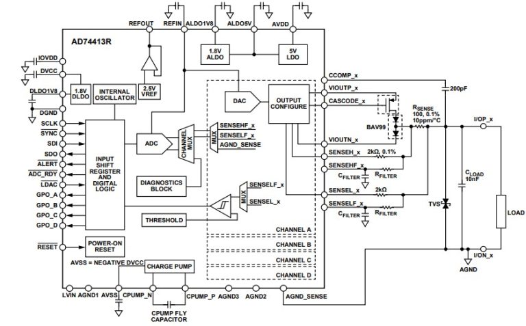
Figure 3: AD74412R/AD74413R block diagram
Both products feature reconfigurable module channels that enable the design of remotely controllable systems quickly and easily without the need for extensive rewiring. This greatly increases the speed and flexibility of implementation for manufacturers and industrial operators, allowing them to make changes without significant increase in costs and downtime.
The AD74412R and AD74413R are four-channel software-configurable input/output solutions for building and process control applications. They include functionalities for analog output, analog input, digital input, and resistance temperature detector (RTD) measurements, all integrated into a single-chip solution via a Serial Peripheral Interface (SPI). The kit features a 16-bit Σ-Δ analog-to-digital converter (ADC) and four configurable 13-bit digital-to-analog converters (DAC), offering four configurable input/output channels and a set of diagnostic functions. Both AD74412R and AD74413R include a high-precision 2.5 V internal reference voltage source to drive the DAC and ADC, providing multiple input/output modes.
ADI Innovative Connectivity Technology: 10Base-T1L
New buildings are equipped with advanced technologies that can remotely control HVAC systems, detect space occupancy, automatically control lighting and monitor environmental conditions, making these buildings more sustainable while also improving the safety and comfort of building occupants. ADI has developed advanced measurement, connectivity, and processing technologies aimed at improving the sustainability of both new and existing buildings. These technologies support the healthy development of buildings, facilitate building renovations to reuse twisted pair infrastructure, and connect modern systems through 10BASE-T1L Ethernet.
The fundamental difference between 10Base-T1L and traditional Ethernet is the use of two wires. Conventional Ethernet typically uses three wires or more, and reducing the number of wires significantly lowers the overall installation requirements. Traditional Ethernet requires specialized cables, while 10Base-T1L can operate with standard twisted pair cables, addressing the challenges of on-site layout and installation. Essentially, it allows achieving 10 Mbps Ethernet speeds using regular twisted pair cables.
Figure 4 shows the general topology of the entire communication link in building automation. The rise in data volumes has led to the realization that traditional solutions are approaching their physical threshold. Moving the intelligence to the edge, enable sensors and actuators to exchange high volume of data. Therefore, the building controller in the middle plays a crucial role in bridging the gap, converting the analog signals collected onsite into digital signals, and finally sending them to the server.
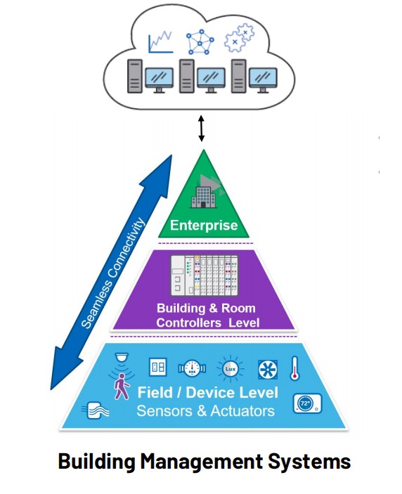
Figure 4: Simplified diagram of building automation communication link process
RS-485 is still a relatively mainstream method in building automation, having been widely used in almost every industrial and residential sector for decades. Its primary feature is its two-wire system, which is very convenient to use. The daisy chain configuration is also easy to install and set up, with communication speeds and distances reaching up to 38.4kbps and 1.2km, respectively.
Although RS-485 is widely used in building automation, there is a need for technological innovation. Through these years, several issues have arisen, such as the difficulty of debugging this architecture. A failure in a single device node can compromise the entire bus network, requiring a systematic dismantling and inspection prior to reinstallation. Large smart buildings such as airports, stadiums, or commercial structures, this issue can translate into a substantial operational burden.
Typical smart buildings consist of controllers and various nodes that make up the building automation system, and connecting easily to all these devices is not straightforward. Excelpoint recommends ADI’s classic switch product, the ADIN2111, which is compatible with IEEE 802.3cg and 10BASE-T1L standards. It facilitates the introduction of Ethernet into point-to-point and ring network configurations for controllers and edge nodes, reducing the load on controllers and simplifying upgrades.
The ADIN2111 is a low-power, low-complexity, dual Ethernet port switch. It incorporates a 10BASE-T1L PHY and a Serial Peripheral Interface (SPI) port, designed for low-power constrained nodes. It is targeted towards industrial Ethernet applications and complies with the IEEE® 802.3cg-2019™ Ethernet standard, making it suitable for long-distance 10 Mbps single-pair Ethernet (SPE).
Figure 5: ADIN2111
The switch (cut through or store and forward) supports various routing configurations between the two Ethernet ports and the SPI host port providing a flexible solution for line, daisy-chain, or ring network topologies. The ADIN2111 can be used in unmanaged configurations where the device automatically forwards the traffic between the two Ethernet ports.
The ADIN2111 supports cable reach up to 1700 meters and features ultra-low power consumption of 77 mW. Its two PHY cores support 1.0 V p-p and 2.4 V p-p transmit levels as defined in the IEEE 802.3cg standard, and it can be powered by a single 1.8 V or 3.3 V power rail.
The device integrates the switch, two Ethernet physical layer (PHY) cores with a MAC interface and all the associated analog circuitry, and input and output clock buffering. The device also includes internal buffer queues, the SPI and subsystem registers, as well as the control logic to manage the reset and clock control and hardware pin configuration.
The ADIN2111 has an integrated voltage supply monitoring circuit and power-on reset (POR) circuitry to improve system level robustness. The 4-wire SPI for communication with the host can be configured to OPEN Alliance SPI or generic SPI. Both modes support optional data protection or cyclic redundancy check (CRC).
Power over Ethernet (PoE) Solution
SPoE (Single Pair Power over Ethernet), previously known as PoDL (Power over Data Lines), is designed to complement the earlier mentioned 10base-T1L technology. For instance, after customers use the two-wire 10base-T1L Ethernet technology and require self-powering, this feature allows the endpoint to both transmit data and provide power over a single twisted pair, enabling the creation of very thin panels. self-powered endpoints can proactively transmit status updates periodically and according to schedule, instead of just passively receiving queries from the main station.
Excelpoint recommends the LTC9111, an IEEE 802.3cg compliant Single-Pair Power over Ethernet (SPoE) Powered Device (PD) controller. Its wide 2.3V to 60V operating range capability, combined with polarity correction, makes the LTC9111 particularly well-suited for classification-based systems in building and factory automation.
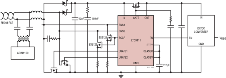
Figure 6: LTC9111 block diagram
SCCP-based classification ensures that Power Supply Equipment (PSE) only provides full operating voltage when a valid PD is connected. The LTC9111 drives two external N-channel MOSFET switches during classification with micropower operation to minimize reservoir capacitor requirements. An external N-channel MOSFET switch isolates the output capacitance from the connector during classification and inrush.
When the PD input voltage exceeds the ON voltage threshold of the configured class or after a mandated delay, the voltage monitor can enable the external MOSFET. The EN output is asserted following a controlled ramp-up of the GATE pin. The MOSFET is disabled when the input voltage falls below the OFF voltage threshold for the configured class. The LTC9111 drives a pair of external low-side N-channel MOSFETs with a low start-up voltage of 1.6V for polarity correction with reduced power losses.
Summary
Excelpoint believes that ADI’s innovative technology and systems expertise are helping to shape the future of the smart building industry. Their products and solutions offer configurable, simplified, and high-performance development trends for smart building control systems, while also laying the groundwork for future technological innovations in the market, enabling better preparation for various challenges.
© 2024 Excelpoint Technology Pte. Ltd. All Rights Reserved.